INCH-POUND
MIL-DTL-85667/7B
2 September 2004
SUPERSEDING
MIL-B-85667/7A
28 January 1991
DETAIL SPECIFICATION SHEET
BOLT, SLEEVE, PROTRUDING HEAD, STRAIGHT SHANK,
CRES 304 SLEEVE, NICKEL ALLOY 718 PIN,
125 KSI Fsu, 220 KSI Ftu, 450º
Inactive for new design after 4 April 1998
This specification is approved for use by all
Departments and Agencies of the Department of Defense.
The requirements for acquiring the product described herein shall consist of this specification sheet and MIL-B-85667.
+.015
(a)
LENGTH -.010
H
UNTHREADED +.005 (a)
Q
T
PIN LENGTH
-.010
REF (f)
ØA (d)
P (g)
CHAMFER 45°
ØD (e)
REF.
TO APPROX.
(2)
ØF
20° MAX
DEPTH OF
+.010
+.000
R -.000
P
R -.010
THREAD
REF (f)
THREAD
ØF
DIA. (c)
X OR Y
PIN
MILITARY
PART NUMBER
STAMP GRIP
SLEEVE
F.T.
DASH NO.
BOLT +.010 (a)
HERE
40°
(b)
MANUFACTURER'S
DESIGN -.005
35°
IDENTIFICATION
GRIP
INK STAMP OVERSIZE
BOLT DESIGNATION
.015/.005 X 45° ±5°
WHEN APPLICABLE
LOT TRACEABILITY IDENTIFICATION SYMBOL
(SYMBOL USED IS THE MANUFACTURER'S OPTION)
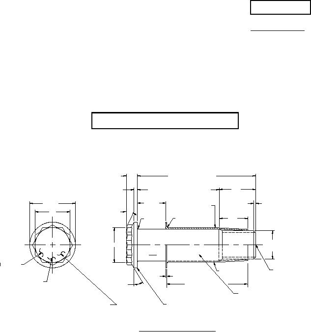
FIGURE 1. Flanged tension head bolt.
(a) Grip lengths are available in .0625 increments.
(b) Dimensions of non-structural flange thickness is established by sleeve bolt assembly installation
requirements allowing no threads in bearing.
(c) Threads shall be in accordance with AS8879. Thread major diameter (T.D.) shall be in
accordance with Table I.
(d) 1. For sizes .190 thru .375, dimension "A" shall be concentric to dimension "D" within .008 FIM.
2. For sizes .437 thru .625, .012 FIM.
3. For sizes .750 thru 1.000, .020 FIM.
(e) 1. For sizes .190 thru .375, dimension "D" shall be concentric to thread pitch diameter within
.006 FIM.
2. For sizes .437 thru 1.000, .010 FIM.
(f) Reference dimensions are for design purposes only and are not an inspection or manufacturing
requirement.
(g) Protrusion will vary according to taper to provide expansion as given in Table I.
AMSC N/A
FSC 5306
For Parts Inquires submit RFQ to Parts Hangar, Inc.
© Copyright 2015 Integrated Publishing, Inc.
A Service Disabled Veteran Owned Small Business